5 minute read
 FPGA
FPGA
RedShark Replay: Although four years old, this, one of our most popular articles is as relevent today as it was back then. FPGAs are modern miracles of technology. They're silicon chips whose hardware configuration can be set up and changed with software. They provide the flexibility of software with the speed of hardware, and are what allow small companies to build products with big capabilities. FPGA expert Tony Cole reports
FPGAs are found in low to medium volume electronic equipment such as Digital Video Converters, Capture Cards and External Video Recorders. Most companies don’t talk about what’s in their products but some do. Atomos, for example:
"The Atomos's Ninja[HD Video Recorder takes uncompressed 10-bit HD/SD video from HDMI, compresses it in to Apple ProRes, and then formats and stores it on HDD/SSD, all in real time."
In their Ninja FAQ Atomos states
“the powerful FPGA deals with input and output, the user interface, the touchscreen and processing the video itself.”
In this article I will describe what FPGAs are, where they came from, what they can do and why they are used.
You can think of FPGAs as circuit boards that can be re-designed every time they reboot. They’re not quite like the analogue printed circuit boards that you find in a transistor radio because they’re digital (which means that they calculate numbers rather than “signals”), but you could say that reprogramming an FPGA is the digital equivalent of taking a vacuum cleaner and reprogramming it to be a toaster.
Digital electronic integrated circuits are built from transistors, and today there are millions or even billions of them on one chip. Each transistor is essentially a tiny switch. To make them useful, they are configured into “memory cells” and “logic gates” It only takes a few transistors to make one of these.
A memory cell can hold a 0 or 1. Actually the 0 and 1 are voltage levels within the chip, where 0V or anything up to a threshold of about 0.8V is a 0 and anything above is a 1, but this varies depending upon the device. The point is that the voltage “means” 0 or 1. That is what “digital” means in “digital electronics” - a binary digit, 0 or 1. This is called a bit.
If you use a string of these bits you get a binary number, e.g. 8-bit, 16-bit, 32-bit and 64-bit numbers – you might have seen these numbers in products like Intel’s 32-bit and 64-bit processors.
An 8 bit number can express 256 levels and a 16 bit number can represent 65 536 levels.
Logic gates are an abstract logical or mathematical idea where one or more inputs produce an output depending on the type of gate. These inputs and outputs are considered to be “bits”, 0 or 1: nothing else.
There are only three basic logic gates and from these any other type of logic gate can be constructed by connecting them together in various ways.
An important device in digital electronics is the Clock, which synchronises all the different elements of a chip. You will of heard of Megahertz (MHz) and Gigahertz (GHz): these are the clocking frequencies. Your desktop PC is possibly clocking at 2GHz, which means 2 billion (2,000,000,000) times per second!
Memory cells, logic gates and clocks are the building blocks of digital electronics. Connecting them together, engineers can build all the components of a processor and perform any specific logical task they wish: binary number “adders” and “multipliers”; CPU instruction decoders, registers and caches; as well as bespoke blocks like digital video codecs and image processors, to name a few.
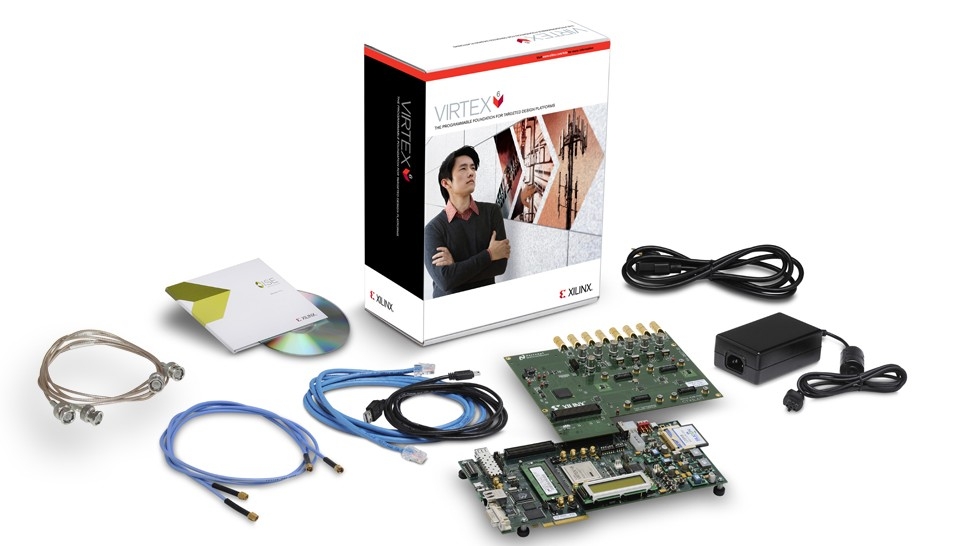
FPGAs were invented as long ago as 1984-5 by Xilinx. Before that there were only simple discrete logic chips (containing one to six logic gates), Programmable Read Only Memories (PROMs), Programmable Logic Devices (PLDs) and Gate Arrays.
Gate Arrays were a “sea” of thousands of unconnected logic gates on one silicon chip which were connected at the last stage of the device’s manufacture to the product design engineer's configuration. This was an expensive process, but still cheaper than getting your own chip designed and manufactured.
PLDs were tens of logic gates connected by internal programmable interconnections. These devices essentially “soaked up” discrete logic ICs (integrated circuits) in to one device, thus reducing the number of ICs, circuit board connections and overall board size in the product. Because they were programmed by the end-product manufacturer they were cheap to configure for many different purposes.
PROMs, although usually used to store computer programs, could also be programmed and used as logic blocks to reduce the number of ICs on a circuit board. This required some additional circuitry to achieve similar functionality to a PLD. But because the PROM was a logic input-to-output Look Up Table (LUT), any combination of inputs could produce any required combination of outputs (a universal “truth-table” that could represent combinations of logic gates connected together), which was not always possible with PLDs.
The FPGA invention was to use the PLD programmable interconnections with many PROM logic Look Up Tables (LUTs) to achieve a much more powerful and flexible device. The first device had an equivalent of hundreds of logic gates. Much more than the PLD.
Today many FPGAs are RAM based (actually, the PROM LUTs and interconnections are RAM based) and are configured before the FPGA starts processing, so making them easy to reconfigure.
Today FPGA design and manufacture are cutting edge silicon technologies on a par with processors from Intel. In fact the high end FPGAs contain around 7 billion - that’s seven thousand, thousand, thousand - transistors on a single silicon chip!
The top-end Xilinx FPGA is manufactured using 28nm lithography, while Intel's Core i7 Extreme uses 32nm. What does this mean? Essentially Xilinx silicon components (e.g. transistors) are smaller so they can fit more on the same sized silicon chip. Smaller silicon components usually means more components and functionality, a faster device and lower power consumption.
FPGAs are found in a wide range of applications. The very high end devices (usually costing $1000's) are typically used by engineers when designing their own custom silicon chips called Application Specific Integrated Circuits (ASICs). These ASICs cost millions of dollars to design and prepare for manufacture, but are very cheap on a per unit basis after that – much cheaper than the equivalent FPGA, and so are used in high volume products like cameras and camcorders. Because ASICs are not re-programmable the design engineers want to get it right first time and not waste effort and potentially millions of dollars having another go - so they often use large FPGAs (among other things) to thoroughly test their design before committing it to silicon.
Why use FPGAs if they cost so much? The smaller FPGAs are cheap, starting from a few dollars each (actually these are call by another name: Complex PLD or CPLD). There is a whole range of CPLD/FPGA devices.
Mid-range FPGAs can contain specific interfaces like high speed serial links used in networking (e.g. Gigabit Ethernet, Fibre Channel), PCI Express® (PC expansion slot interface) and Video (e.g. HDMI and HDSDI). They can also contain highly optimised “hard macro” blocks such as memory, arithmetic units, processor cores (e.g. ARM) and so an entire system can be placed on a single chip (called System on Chip or SoC) and so requiring very few external devices.
Why not use a processor (CPU) instead of an FPGA? In many applications, a CPU is more appropriate, because this type of processor is very good at “general purpose” work. But the crunch comes when the processor is not fast enough for the processing job, or the required processor is just too expensive.
Real time video compression is a good example. The amount of uncompressed HD video data (per second) is huge. A very fast, expensive and power hungry desktop type processor would be required to perform the compression algorithm in software. But because the compression algorithm is very repetitive, it can be broken down in to many duplicate parallel parts in an FPGA and processed at a lower speed, so requiring a relatively inexpensive device. Also, because the FPGA is (usually) reprogrammable within a product, the compression algorithm or functionality can be changed at the press of a button. This makes hardware as configurable as software and you can resuse the hardware that is already there for different tasks instead of making the device bigger and more expensive.
When you download “firmware” for your FPGA-based device, at least part of this update is likely to be an update for the software that configures the FPGA
FPGAs are ideal for low to mid-volume specialist video devices that don’t justify the cost of creating ASICs.
Field-Programmable Gate Array, where the “field-programmable” means that they can be configured after manufacture in the silicon foundry.
Tony Cole is an Embedded Systems engineer with 26 years experience involving product, system, electronic, FPGA and firmware architecture, design and implementation. In recent years he's been working on FPGA-powered devices that use a spinning array of LEDs to create circular or cylindrical video images.
Tags: Technology

RedShark 2020 @ All rights reserved.

Comments