
4 minute read
In the final part of our series on how to build a workstation, we cover the fun part. Putting it all together. It lives, it lives!
Read parts 1, 2, 3, 4, 5, and 6 of this series.
It’s been pointed out that while we’ve gone over selecting workstation parts in a bit of detail, the part that worries people most is putting it all together. That won’t bother anyone who’s been following the series just to catch up on workstation component specifications, but there are savings to be made with a home build and, perhaps more importantly, if it breaks, you can confidently fix it faster than more or less anyone else possibly could.
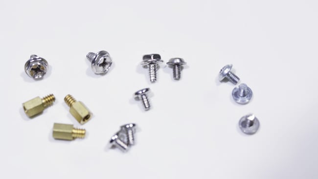
The good news is that all you’ll need is a single screwdriver, but beware: there are two different screw types that look alarmingly similar and will screw into and screw up each others’ threads quite effectively. One is metric, M3, which is used to hold things like optical media drives (if you really feel like you need one) and one is a #6-32 UNC screw. The general rule of thumb is that more or less everything is UNC except DVD drives and hard disks and SSDs in the 2.5” laptop format. If it won’t go, don’t force it.
Having got off to a suitably confounding and worrisome start, let’s just be clear that almost everything else is very straightforward and if we don’t force things that don’t want to go, we won’t break anything. We can’t possibly cover every feasible combination of hardware that exists in the world, although we can certainly hit most of the common problem points.
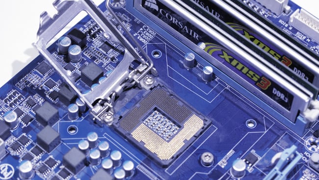
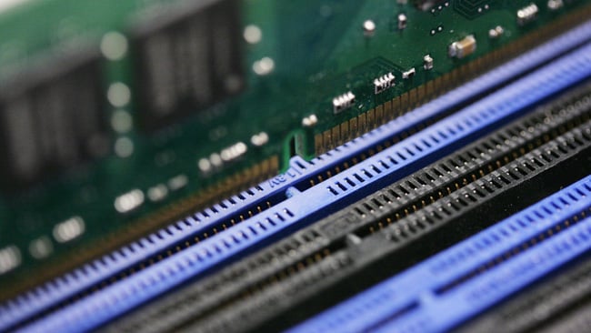
The first thing to do, having put on our anti-static wrist strap and pulled everything out of the boxes, is to shove the memory modules into the motherboard. Sometimes sticks of RAM need a fairly firm push to get them in and, for that reason, it’s often better to put the memory in while the motherboard is flat on a desk so we aren’t flexing it when it’s on its standoff pillars inside the case. Then – and this is a really common error made even by old hands – remember that some CPU coolers need a backing plate bolted through the holes provided for that purpose on the motherboard. Sometimes it’s necessary to loosen a few screws and remove the supplied cooler clamp. Most coolers that come as standard with CPUs will fit the motherboard as supplied, but it’s worth checking.
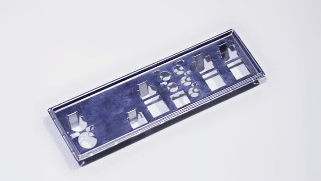
Next, put the I/O shield into the back of the case, which is there to block stray radio interference generated by the high-speed electronics inside. These can be a pain in the neck – they’re supposed to just pop in but sometimes don’t if the parts are cheap or the factory was having an off day. If it’s loose, don’t worry – the motherboard will hold it in. If it’s too tight, consider putting it aside – it looks slightly ugly but it’s unlikely to cause any radio frequency interference issues in the real world.
The motherboard sits on top of short brass standoff pillars. No, you can’t just screw it straight down to the bottom of the case; nothing will fit and it will short out on the metalwork (yes, people have done this.) The case will come with a set of holes and it’s a matter of figuring out which holes on the motherboard line up with which holes on the case, screwing the pillars into the case and then screwing the motherboard down on top of the pillars.
![]()
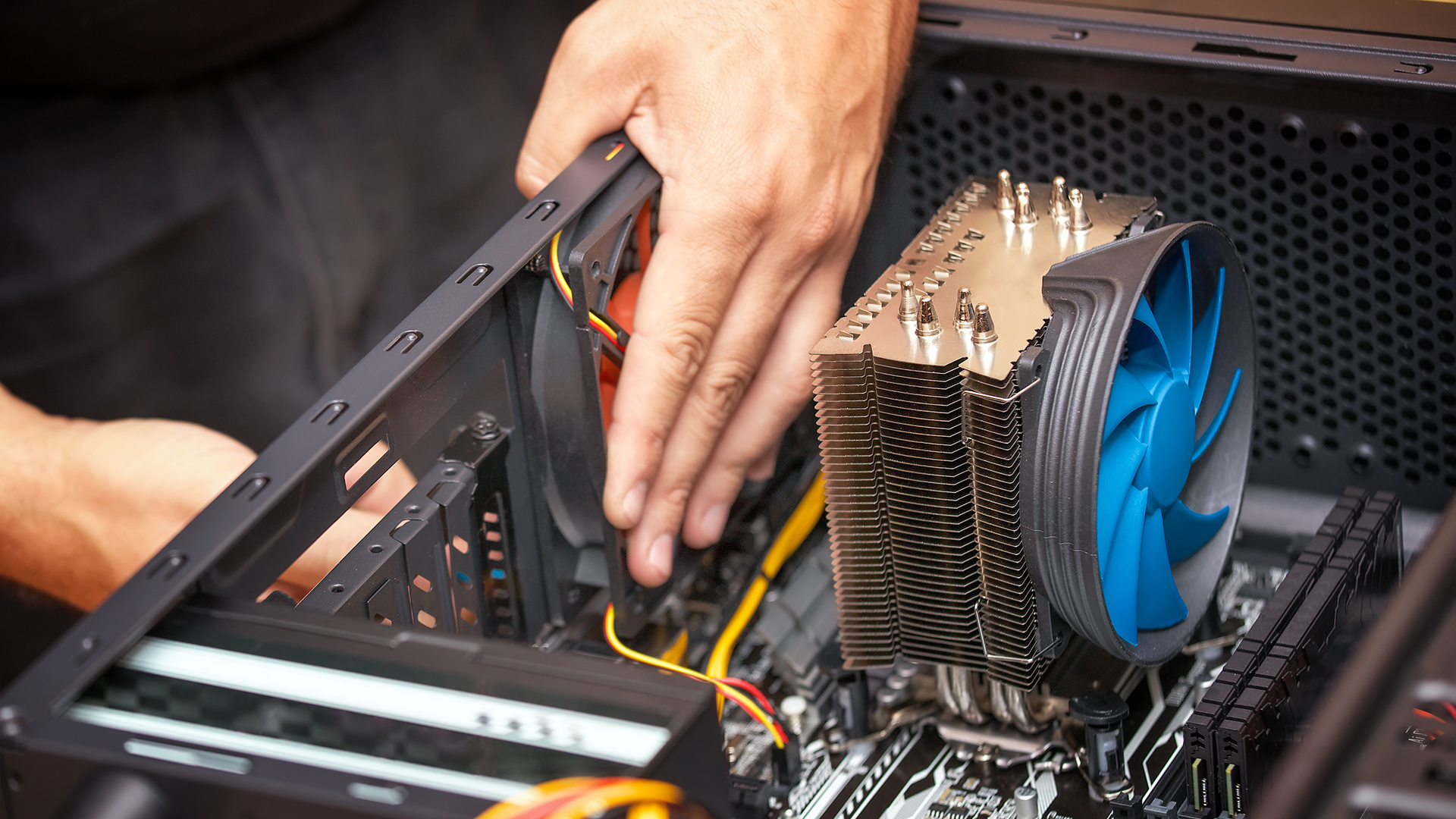
Most people will fit the CPU at this point. Dropping the chip itself into place is usually pretty easy since a zero-insertion-force socket is often provided. Fitting the cooler on top of the thing can be a little nail-biting since they often use quarter-turn plastic latches that take a bit of force to snap into position. The cooler needs to push down firmly on top of the chip for maximum heat transfer and this may be a good time to find a YouTube video of someone fitting a cooler of the same design.
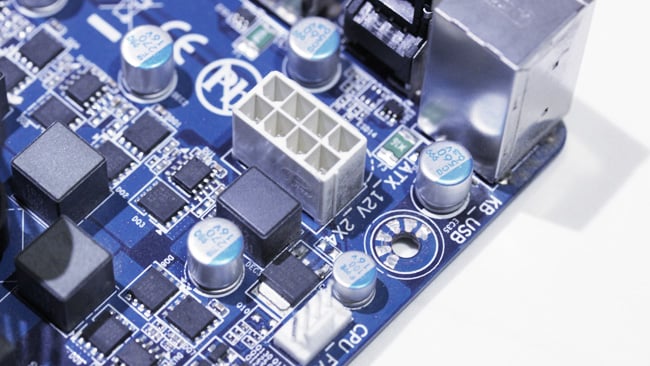
Now is the time to fit more or less everything else. The power supply is often the bulkiest item and most of them have at least some permanently attached cables, so perhaps do this the last. If you have just one M.2 drive, slot it into the motherboard. If you have 3.5” spinning disks, bolt them into the bays in the chassis (you made sure there were enough, right?). Modern cases generally include 2.5”-compatible drive bays, though it’s possible to get adaptor kits to put 2.5” drives in 3.5” bays.
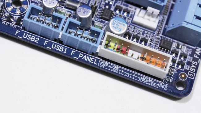
At this stage, connect the front panel controls which often means the On switch and On light. Of all the staggeringly complicated things we’ve managed to standardise, the “On” switch is still a matter of consulting the motherboard manual to figure out what goes where. If the LEDs don’t light up, reverse the connector (getting it wrong doesn’t hurt, it just doesn’t work). This may also be the time to connect front-panel audio and USB connectors, though be careful: it’s not unheard-of for particularly long expansion cards to block connectors on some motherboards and it’s also quite usual not to have all of the USB connectors in use. Any spare can sometimes be routed to plates that fit unused expansion card bays at the back of the machine.
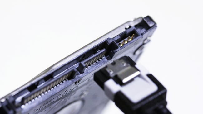
Finally, shove in the PCIe cards – just a graphics card on many systems – and start cabling-up. It’s hard to make PC innards look tidy, but it’s a good idea to zip-tie cables out of the way to maximise cooling airflow and minimise the potential for short circuits on unused power cables. SATA connectors can be a little delicate; particularly, avoid sharp downward twists as they can snap off.
Having tightened all the screws and double-checked your work, it’s time to hit the power button for the first time and yell “We’ve got a heartbeat!” if everything works as intended.
Next comes installing the operating system and applications, but – unless there’s a huge demand for it in the comments – that’s something we might leave for the thousand online tutorials which already exist.
This concludes our series on building workstations from scratch. In the future, we hope to demonstrate the procedure using some typical parts – watch this space.
Tags: Technology

RedShark 2020 @ All rights reserved.

Comments