5 minute read

Replay: In Part Two of our series on video processing and standards conversion, Phil Rhodes gives us a lesson on video scaling and why a hardware solution is the way to go.
Bigger, as the saying goes, is better. Notwithstanding the most traditional interpretation of the phrase, this is certainly borne out in the experience of cinema-goers, who have traditionally been more impressed with greater screen size, a larger bucket of popcorn and anything up to an imperial gallon of carbonated sugar water that turns your tongue blue. Making pictures bigger, however, involves more technology. Perhaps surprisingly, so does making them smaller, as was discovered by people who noticed the problems of aliasing on Canon's famous 5D Mk. II camera, whose sensor was so much larger than the output image that adequately scaling it down became a serious technical issue.
Aliasing, or the blockiness of digital images, is a characteristic that more or less everyone knows. It's the effect created by any attempt to fit non-rectilinear objects onto an imaging surface that's made up of pixels. This affects both displays and cameras, and whereas displays invariably have pixels in a regular grid, cameras such as the 5D Mk. II cluster the pixels of the sensor together in irregular shapes when in video mode, creating unusual artefacts.
At this point, it's worth understanding some of the formal information theory about aliasing. Aliasing is caused when a digital sampling device attempts to sample a signal containing information at a higher frequency than its Nyquist frequency. Practically, in terms of imaging, this could occur when a camera's lens projects a high-resolution image onto its sensor or in a scaler, attempting to reduce the pixel dimensions of an existing digital image.
The test image we're using here is called a zone plate and is designed to reveal aliasing clearly; on a straight line, the same thing is visible as stair-strepping. A zone plate reveals aliasing as sets of additional circles that aren't concentric with the original circles. In this example, we can see sets of curves appearing at the edges of the zone plate square when we omit every other pixel. In order for this to look right, you'll need to ensure that your web browser and operating system is set up so that it doesn't scale images; look for a "zoom" option and set it to 100%. If the square on the left doesn't look like clean concentric circles, something is wrong.
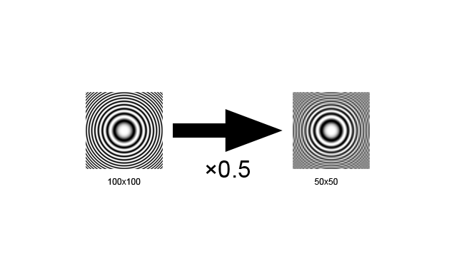 [Figure 1: Aliasing.]
The problem can be solved by removing the high-frequency information from the signal - that is, blurring the image - before we downscale. Notice that the half-resolution version on the far right barely looks different to the version in the middle, even though it only has a quarter the number of pixels.
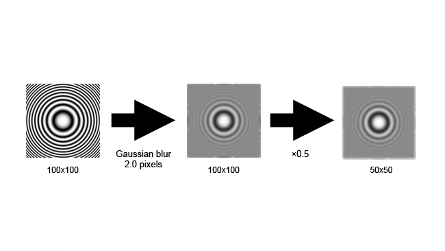 [Figure 1a: Filtration then aliasing]
Once an image has aliasing, it cannot be removed; there is no way to tell the difference between high frequency (that is, sharp) true picture detail and the artefacts of aliasing. Sadly, this filtration is an imperfect process: camera designers must compromise between avoiding aliasing and compromising sharpness. After-market low-pass filters for Canon DSLRs can remove aliasing in video mode, but the result is often noticeably softer.
Scaling up has problems of its own, although in the earliest computer graphics applications, things were different. In the late 70s and early 80s, pictures were often drawn as vectors, by directing the electron beam of a cathode ray tube between points to draw a line. The more modern technique is the raster display, scanning an even field of stripes then turning the beam on and off at various points to build up an image. The technique was used in some of the graphics rendered for the original Tron and, until very recently, was the de-facto approach for high contrast displays, such as the heads-up display in military aircraft. The advent of TFT and OLED displays with sufficient resolution and contrast for those jobs mean that we're unlikely to see new vector display designs. However, the same technique makes modern computer fonts scalable, where the outline of each character is stored as a series of lines and curves, as opposed to as a grid of pixels.
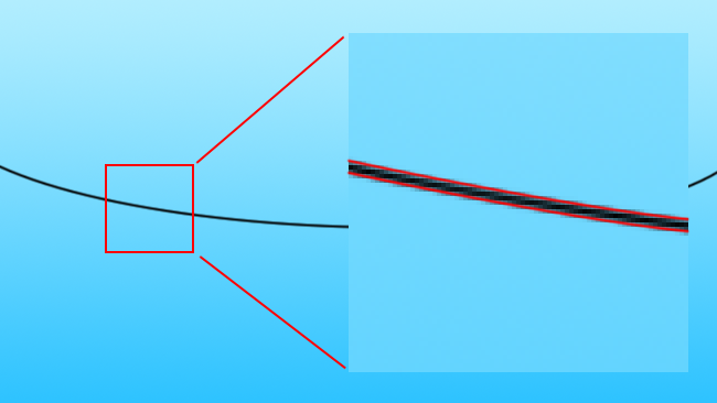
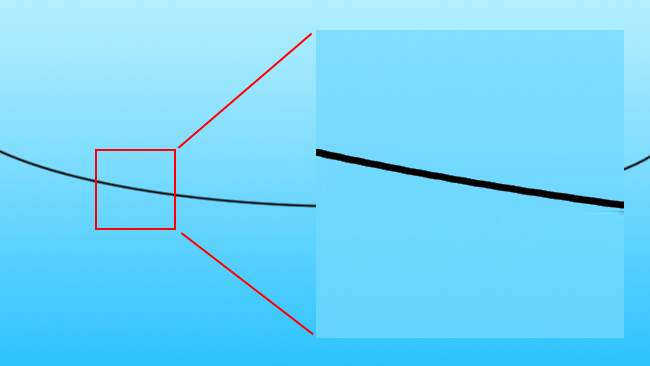
One key thing you can do with a vector image that you can't do with a raster one is to scale it simply by multiplying the coordinates, which determine the position of each line by a scaling factor. Scaling raster images - that is, more or less all modern computer graphics - is much, much more complicated. A vector image encodes based on what the subject it represents is ("a red circle"), whereas a raster display simply encodes what colours exist at what locations, giving us no information about what might exist between those locations. This distinction becomes important when we begin to consider approaches to scaling raster images. We might, for instance, encounter a photographic image of an overhead electrical cable against the sky, a black line against blue.
 [Fig. 2: Black line against blue]
To upscale the image, we need to create more pixels. A naïve algorithm might simply use linear interpolation, assuming that the missing values must lie on a line between the values we have (this is often referred to as "bilinear" in applications such as Photoshop, as they apply the interpolation in both axes of the image). Let's scale up four times, which is a similar situation as if we were taking an SD image and scaling it to 4K.
 [Fig. 2a: Black line against blue, 5x, bilinear interpolated]
This is the familiar sort of basic scaling that is often done by web browsers and desktop photo viewers. As we can see, there are two problems here. The first problem is the obvious side-effect of upscaling an image: the edge of the wire has become soft and blurry. The second problem is that there are artefacts in that blurriness which make it look more like a digitally synthesized image and less like in-camera photographic softness, which might be more acceptable.
There are better algorithms (the bicubic, gaussian, etc) which will more accurately simulate an optical blur in these circumstances, but they're not really adding much to the situation. The fundamental, underlying problem with this is that the computer doesn't have our understanding that what it's seeing is a black object against a blue sky, that the black and blue areas are fundamentally different and should not blend into one another. This brings us back to our consideration of vector imaging above: what we really want is a definition of where the edge of the wire is, so that we can scale it accordingly:
 [Fig. 2b: Black line, with vector overlay]
Until we can build a computer that has a human-like understanding of the contents of an image, which would almost certainly imply an advanced artificial intelligence, there is no perfect solution to this. As humans observing the image, we can see where the vector lines defining the edges should go; however, no computer system can do so, at least not to that level of refinement. The best current solutions, such as those used by high-quality upscalers in both software and hardware, are based on the assumption that sharp edges in the original image should probably remain sharp edges in the upscaled image. Interpolation of pixel values is therefore performed between edges, but not over the top of edges. This assumption holds well enough that the results from scalers using these more advanced techniques can look enormously better than what we might predict, given the amount of information that has to be generated by the scaler.
 [Fig. 2c: Black line, upscaled by (something a bit like) Teranex]
The downside, of course, is that identifying edges in an image - a single human hair against a background, for instance - can never be an entirely reliable process. This is particularly true when the image is noisy, which can mean either traditional noise generated by a sensor or simply lots of chaotic shapes and motion from the scene itself, or instances when edges which should be separated are close in colour and poorly defined. It is a task that can be made almost as complicated as the designer of the algorithm wants to make it. The processing power required to do this can become enormous, too, and it's only modern techniques whereby a single process is performed against multiple chunks of image data simultaneously (called SIMD, for single instruction multiple data) that makes the approach practical for real-time processing. This is the same thinking as that applied to modern graphics cards, which we talked about recently with respect to the GeForce GTX 980 and Resolve.
Hardware devices such as Teranex probably implement their custom SIMD capabilities on FPGAs, programmable devices with a large number of individual logic elements which can be connected together to form useful devices and are well-suited to creating arrays of devices for repetitive work. We've talked about those before too, in the context of image processing in cameras. They don't have the same enormous raw performance as the custom silicon created by Nvidia, but for niche applications like standards conversion, they make it possible for electronics, at least on a small, per-pixel scale, to behave in a way that aligns them much more closely with the way humans expect things to look. The future, given the rate at which technology is currently advancing, looks glowingly rosy. Perhaps one day we won't need to shoot 4K at all.
Tags: Technology

RedShark 2020 @ All rights reserved.

Comments